
2D Plotter Project
The aim of the project was to design a 2D plotter, that would be able to draw graphics with the use of a ballpoint pen. The device is based on Computer Numerical Control principles.
Design assumptions: simple mechanic system, good quality plots, low total cost and easy to modify the frame.
Project overview:
● 3D model - Autodesk Inventor
● Frame static and modal analysis - Autodesk Inventor
● Motion control - Easy CNC open-source software
● Inkscape + modified plugin for converting raster images into G-Code
● Control board and drivers: Arduino Mega + RAMPS shield + 2 x A4988
● Actuators: stepper motors (X-axis and Y-axis:) and servo motor Z-axis
● 3D printed parts
Design:
The movement along X-axis and Y-axis is ensured by two stepper motors, then the movement along Z-axis by one mini servo motor. Stepper motors were chosen because of their simple construction, high reliability, as well as precise positioning and repeatability of the movement. Moreover, errors do not cumulate from one step to the next. Another important advantage is the capability to accurately operate in an open-loop control system. For simple the task of moving pen upwards and downwards mini servomotor was selected.

-
Idler pulley
-
Plotting head
-
Linear guides
-
Stepper motors
-
Driving pulley
-
Timing belt
-
Table
Plotter workflow:
Plotter workflow starts with a vector graphic created in Inkscape. To plot simple shapes, including:
rectangles, polynomials, ovals, etc., users can use built-in tools. Shapes consist of vectors would be directly transformed to tool path, then with the use of Laser Tool plug-in into G-Code. However, if the user would like to plot raster images, the case becomes more complicated. The first image have to be imported to Inkscape workspace, then, using the trace bitmap tool, convert it into the path. The mentioned tool has several different methods to accomplish this task: brightness cut-off, edge detection or colour quantization. The selection of the method depends on the input image. In addition the higher the resolution of the input image, the better results of the output path. Moreover, raster graphics with transparent background, tend to be easier to convert. The next step is to perform G-Code simulation with the used of CAMotics software. If the plotting tool operates as intended, the user can proceed to the final step. At the final step, plotter search for home position. Then, Easy CNC Controller starts to send G-Code instruction to the machine and plotting begins.

Prototype gallery:


Plotted drawings:

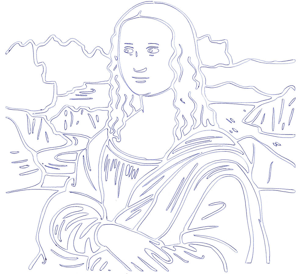

Plotting drawings:

